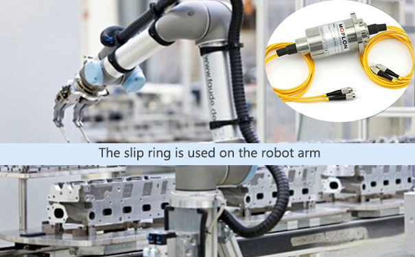
At some levels, we all know what a slip ring is, but in order to understand what a fiber optic rotary joint really is or does? We need to revisit the definition of a slip ring. So putting it out here, a slip ring is an electromechanical device which is used to transmit an electrical signal from the stationary component to the rotatory structure.

Now, the knowing the definition of slip rings makes it easier to understand about as its nothing more than just another alternative to conventional slip ring with a subtle yet defining difference. Unlike, the presence of a contact between the slip ring and brush, in case of a conventional slip ring. The fiber optic rotary joint is devoid of any such contact mechanism.
The fiber optic rotary joint also known as fiber optic slip ring in some cases, is widely used as it transmits optical signals simultaneously as it rotates. is mainly used in robotics, ROVs (remotely operated vehicles), medical equipment, military, and autonomous vehicles.

One of the thing that user might tend to miss out on is the fact that yes the optical rotary joints are highly beneficial. But at the same time, it is not always a smooth sailing while working with it (). The pertinent issue that comes up with the use of is the loss of signal during transmission, which will be discussed ahead at length.
Signal loss and their sources
As mentioned earlier, the loss of signal during transmission with the use of is quite a consistent problem, which needs to addressed as early as possible to get things in order. There are several factors which makes way for such a problem and some of them are discussed below.
Insertion loss
When a device is added to the optical fiber, then such insertion loss takes place. The signal loss in such a case can be calculated with the help of an equation IL= 10 log 10 (pt/pr), where pt is the power of a signal transmitted while pr refers to the power of the signal received. Also, the term IL refers to the insertion loss which is presented in the form of a decibel. According to the standards, a signal loss of 3db refers to the fact that half of the signal is lost in between the receiver and the transmitter.

Insertion loss variation
One of the factors that affect the insertion loss is the rate of rotation, which in turn is affected by the alteration in the coupling conditions. The variation in the insertion loss along with other elements changing reduce the S/N ratio or the signal to noise ratio. Now, when there is a considerable variation, equipment which is sensitive to such insertion loss variation has to be fitted with a exhibiting a 'wow' level (an application which is highly sensitive to lose variation) below +/- 25 decibels. The condition of the at any point of time can be out with 'wow' level. Also, when the 'wow' level rises sharply the ceases to operate in a desired manner.
There are various other factors which affect the loss of loss of signal during transmission. But the above two are the most prominent ones that need to be taken care of.
